This page describes the electrical system in our 2020 Sprinter 170, with a 4 cylinder 2.1L diesel engine.
Main components:
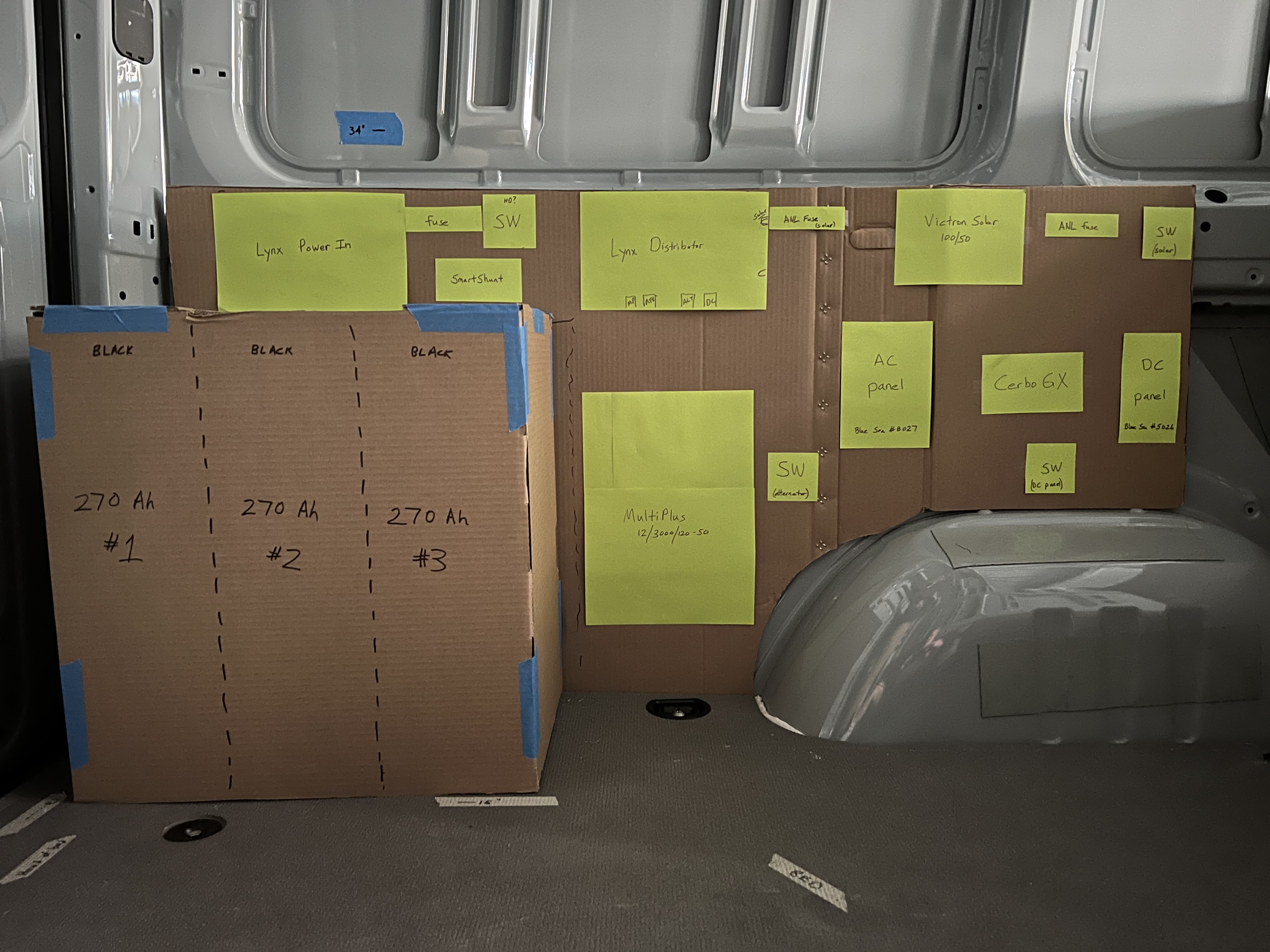
The electrical system is located in the garage, on the driver side, running from the rear to the area just above the wheel well. The electrical system is mounted on a plywood panel, currently shown as a cardboard mockup in the photo below.
It takes a lot of energy to charge a big battery bank. To provide substantial charging power, we have a Nations 280XP alternator with a Wakespeed WS500. Wakespeed and BattleBorn are sister companies now; both are owned by DragonFly. Things to know, based on various conversations with Wakespeed and BattleBorn:
The Wakespeed website has an excellent Buying Guide and other information; click on Learn and look for the How-to Guides.
BattleBorn is a good place to order from. Be sure to order:
Can be hard to find folks who will install a second alternator, perhaps especially true in the Atlanta area. Monster Customs (just outside of Atlanta) installed ours. We agreed for me to do most of the work to integrate with the Wakespeed and my electrical board.
A detailed (but maybe dated?) install thread is here. Some confusion over 2-belt vs 3-belt installations. More here.
To run the 4/0 wires underneath, some installers have used these " commscope bhd 114" hangers. One source: Radio Gagas.
We have 3 BattleBorn GameChanger-3 batteries for total of 810 Ah. These are mounted standing up "tall", with the positive terminals towards the side wall. The batteries are connected together with copper busbars.
The positive busbar is connected to a 500A ANL fuse block with 4/0 cable, which is then directly connected with a very short busbar (approx 3") to the Blue Sea HD-Series 3000 switch (rated at 600A), which is then connected to the Victron Lynx input using a very short 4/0 cable.
The negative busbar is connected to a Victron SmartShunt 500 with 4/0 cable; the SmartShunt is then directly connected to the Victron Lynx (had to make the hole on the Lynx busbar slightly larger to accomodate the M10 bolt on the shunt).
BattleBorn asserts that .5C charge rate (135A per battery) will not reduce battery life. Note that 240A from second alternator, plus 50A from solar, equals 90A per battery. If plugged-in to shore power, the MultiPlus will produce 120A for charging (an additional 40A per battery), for a total of 130A per battery -- still within the allowed charging rate spec. Of course, we don't ever expect to be charging from all 3 sources (solar, shore, and alternator) at once.
Everything in the van will be powered from the batteries; we will not have a transfer switch.
To keep the 810 Ah of batteries charged, we will rely on solar and a second alternator.
We hope/plan to rarely plug into shore power.
Solar consists of 3 x 175 watt Renogy rigid solar panels with Victron 100/50 MPPT controller.
Just an FYI on safety: to completely disable the entire board, you must turn OFF 4 sources:
Note that each of the four connection points has its own MEGA fuse, with rating shown in square brackets []
Note that the Lynx Distributor has only 4 connection points. Instead of adding a second Lynx, the solar controller is connected to the Lynx using the connection points on the right end of the Lynx busbar, which are normally used to add another Victron component. More on this below.
The Multi-Plus is connected to the Lynx using approx 3 feet of 4/0 cable.
The Blue Sea 5026 (ST Blade Fuse Block - 12 circuits with Negative Bus and Cover)
is used for all DC loads except for the RTX-2000 AC unit.
The fuse block is switched with a Blue Sea m-Series 6006 switch.
A Blue Sea m-Series 6006 switch is also provided for the feed from the second alternator.
The SmartSolar controller is connected to the Lynx using the connection points on the right side
of the Lynx. The SmartSolar has breakers at both the inputs and outputs.
Starting from the Lynx, and proceeding to the right, the positive elements are:
Lynx unfused connection point
63A breaker
SmartSolar
16A breaker
wires (#10AWG) continue up to solar panels on roof
The breakers used are DC Miniature Circuit Breaker, 2 pole, with DIN rail mount, by Chtaixi. Compact, comes with mount, and breaks both pos and neg.
Need to verify that the shore power and inverter power are handled as described above. I recall that the inverter output goes through the top breaker pair, and that the bottom breaker pair is unused. I am inclined to run the shore power through a surge protector, and let that device protect the Sprinter from external power issues.
The larger connections were made-to-order 4/0 cable from www.batterycablesusa.com
This is all-copper flexible welding-type cable to facilitate routing of cables.
